
Preparing the quadcopter for the maiden flight I had to open it and inspect all the parts, to know what I was going to fly with and to be able to properly prepare it for the field. I checked how the wiring to the motors was done, the way to change the connections. There is enough wire to connect and disconnect and eventually change the motors in case of need. I'm more for soldering the motors to the ESCs to avoid issues in the contacts. The bullet connectors are string here so I don't expect to have issues.

I have a Sanwa receiver.. PWM

It would be great to have all the files needed to reflash whatever on the quad.

In the quad there are two boards: one for all the ESCs, one for all the electronics. I don't like this a lot as changing a small simple cheap part may imply a huge cost to replace all single board PCB. If I want to upgrade I cannot do that, unless I replace everything. I don't either know if vibrations and torsions due to crashes are good for a single PCB.

The ESCs board connect to the FCB (flight control board) with pin jacks. Hmm... what about collisions again ?

Foam is in place to avoid that the ESCs board slide away from being connected to the FCB (that is a CC3D with OpenPilot)


This is a manual we found on the web that explain the possibility to enable/disable one-shot feature according to the receiver bus type (PWM: one shot disabled.)

Connectors exposed are not good. Dust, water.. I would protect them.

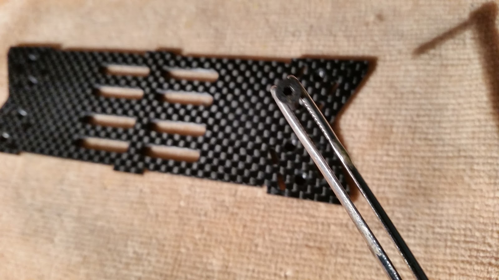
Screw holes are well done. If screws have issues would be difficult to remove them as they are down inside the frame.

Noce idea to use embedded bolts. The screws appear to be good quality and feet well on the screwdriver.


Cam has some pcb parts exposed. I would cover these as well.

I will have to put leds on the legs to ensure the quad orientation is visible when flying VLOS.


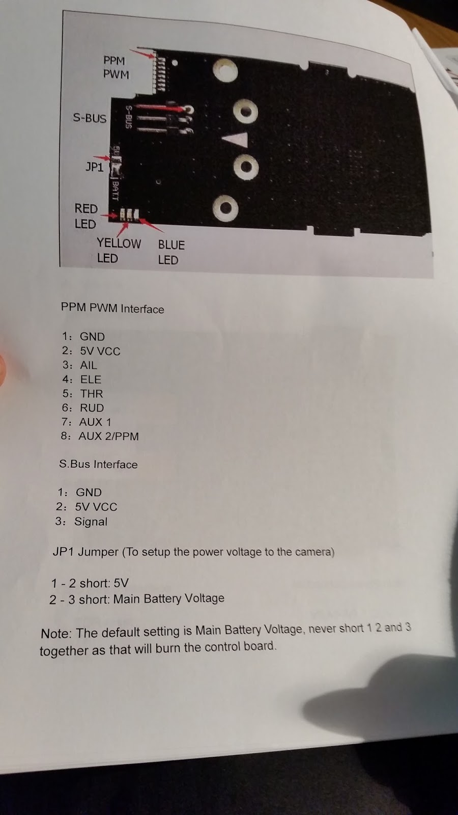
Thanks to the manual I assume being correct for the quad I could connect my PWM Sanwa receiver.


By now I have protected the connectors with some tape. I would fix this somehow better to ensure they are covered and at the same time easily reachable to do tuning. Well... once set how frequently I may need to change software settings using these same connectors again ? maybe they could be positioned internally somewhere.

Time to connect video Tx. I will use channel 1, at band E (5705 Mhz) compatible with channel 1 of my RC805 video rx.
Channels allowed by my RX are:
5705,5685,5665,5645,5885,5905,5925,5945 MHZ


I have put some hot glue (black in the picture) to ensure molex connectors does not move. To have stable image I'm used to do this. This black stuff can be easily removed with no damage to the connectors.

I have removed from the connectors unused wires. What is not needed should not be on board.


Same thing for the PCB connectors I'm soldering to the wires of the video tx using shrinking tube.


It is always a good idea in my view, to add the name of the model on the model itself, so that before flying it is easier to remember to switch the model on the tx as well.


It seems quite mandatory that the rx and the tx video will have to stay on top. Because of this Some more space in the canopy could be a good idea, especially for those that like me, usually put the tx on the quad using a piece of 3M dual lock. To be able to remove electronics from the quad easily.

As the quad is so much open and I want to protect it from water dust objects entering inside and causing damages, i will use some plastic tape to close the quad lower parts.

Not only the body, but also the cam board.


As my tx will be pushing against the canopy, I decided to put some adhesive foam inside the canopy itself.


In this way it is possible to protect from crashes the rx and the video tx.

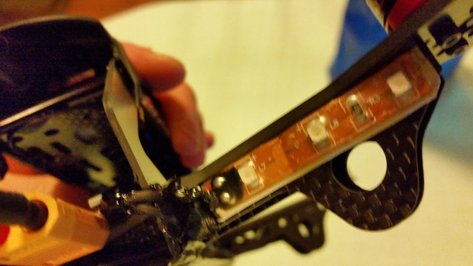
I would have appreciated some led installed on the models by the factory itself. In FPV as in VLOS flight it is always good to understand how the model is oriented. I'm using two led strips that I have put into a transparent shrinking tube to avoid contact with water and scratches on the led strip circuits.


I have used double sided tape to fix led on arms. As I usually do: red on the back, green on the front side. Here I'm adding just red strips as I have no led strips anymore :).


I decided to protect also the battery connector, especially from water. I'm a bit concerned by the battery plug being here. A crash on the connector for whatever reason it may happen, would damage the single pcb. The single pcb is not something I like a lot. Whatever gets broken will imply replacing the whole board.

